Modifying the Test Section
& Instrumentation of a Subsonic Fan

-
A Master group project consists of 3 people
-
A subsonic fan rig at the Thermo‐fluid Mechanics research Centre requires modification to its test section (including blades) in order to improve its performance and to take it to next level of experimental fidelity.
-
The project involves various hand‐on aspects that would include working with machines, manufacturing, measurement and rig control instruments in a laboratory environment.
SUMMARY


Step 8:
-
Light sanding was applied to remove unwanted bits and give a smooth surface
-
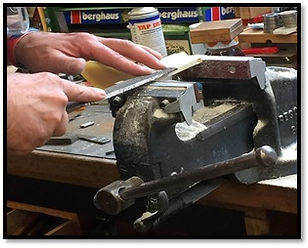
The root of the blades were then filed and machined at the desired geometries to fit into the hub.
-
Then, the blades were pressed into the hub.


Step 5:
-
Repeatedly, the Silicon Rubber was poured gently into the set-up box until it was fully filled.
-
The mould was allowed to fully cure for 24 hours.
-
Then, the master pattern was removed
-
To modify the blades of the fan rig by selecting the most suitable material and determine the most practicable manufacturing technique to manufacture the blades that can operate at a speed range up to 2100 rpm without any failure.
-
To develop an outflow variable controlling mechanism (throttle) to accurately control the air mass flow through the rig by using a manual and/or an automated adjustment method.
-
To install the new instrumentation into the fan rig to understand the fluid flow at the inlet and exit of the fan rig, to be able to obtain the fan characteristic with the new modification.
-
All the modifications are conducted with regard to safety procedure, and should finish on time and within a budget of £600.
Aims and Objectives


1. Manufacturing of Rotor Blades
-
The design of the rotor blades the existing is based on NASA Rotor 67 by Gunn.
-
The chosen material of the blade is Polyurethane F190 Resin, with the add of Aluminium Hydroxide RZ 30150
-
The manufacturing is Two-part Casing.
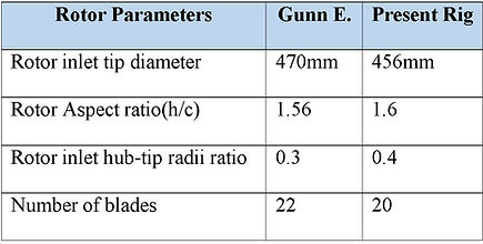
Table 1: The blade's geometry

Figure 2: The CAD given
Figure 3: Mixture of Polyurethane
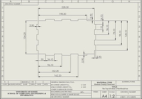
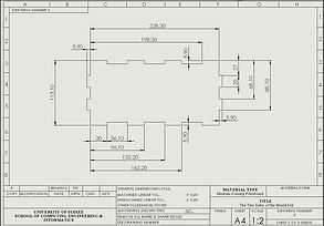
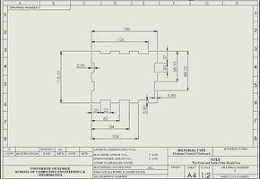
Figure 4: The CAD drawing of the Mould Box

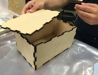

Figure 5: The Mould Box


Step 6:
-
Polyol & Isocyanate resins were poured into two separate containers.
-
Aluminium powder filler was poured into each container. Then, both resins were mixed together.
-
Immediately poured the mixed resin into the mould from the sprue.

Step 7:
-
The cast product was removed (the video)
-
Then,The cast resin was cured for 3 hours.

Manufacturing Method:
1. Creating a master blade by using Fortus 350MC 3D printer
2. Positioning the master blade into the mould box
3. Making the first silicon half-mould
4. Releasing the clay from the silicon mould. Applying the release agent on the surface of the mould.
5. Making the 2nd half the mould.
6. Mixing the polyurethane resin and AlumiumHydroxide, then pour into the silicon mould.
7.Allowing the resin to be cured.
8. Sanding and filing.
Figure 6: Step 1
Step 2:
-
Half side of the master pattern was imbedded in the clay.
-
Creating the registration/alignment keys.
-
Creating the sprues .
-
Sealing the gap at the interconnections.
My main contriubtion for the group were:
-
To find the manufacturing method for the blades
-
To set up the instrumentation to the fan rig.
-
To set up the experimental test for the blades deflection, uniformity of the flow, the best location for the pitot tubes and and fan's performance.
-
Processing the result data by using Matlab.
Contribution
-
The root of the blade made into a rectangular shape by adding the F190 so the root of the blade can be clamped securely
-
A loop of a thin wire is attached to the middle of the blade span, which allows the weight hanger to hook on.
-
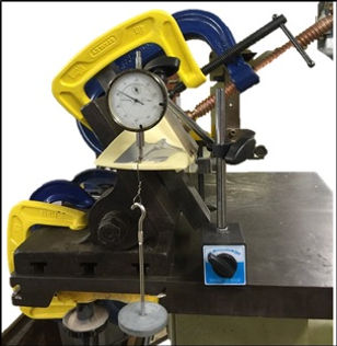
The blade is then clamped at 45 degrees angle so that the leading edge and the trailing edge of the rotor are positioned horizontally. This also ensures a uniform distribution of force is applied to the blade tip.
-
The dial indicator with the magnetic base is set up next to the blade to measure the deflection of the blade when the load is applied.
-
This instrument has a clearly defined point of contact with measure object and its base is properly located on the table, which avoids the error in the setting up and reading the measurement. Its resolution is 0.01 mm, so the reading error of the dial indicator is ± 0.005 mm.
-
The force is applied by adding weight starting of 100 g up to 1000 g with a 100 g increments.
-
After that, higher loads are applied to the tip of the blade by adding 2 kg weight increments until the blade is destructed. The personal protective equipment should be worn to avoid injury from the unexpected broken blade or the falling weight.
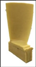


Figure 15: The Deflection Test Setup
Figure 14: The blade for the deflection test
Figure 12: Filing the casting blade
Figure 13:The complete assembly of the blades into the hub
Figure 10: The final mould
Figure 7: The set up of the master pattern into the mould box
Figure 1: Design profile of the current rotor and NASA Rotor 6717.
Note: Note: Hub(black), mid-span(red) and tip(blue)
2. Setting up the new Instrumentation
-
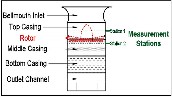
There are 2 stations: at the inlet and outlet of the rotor.
-
12 static (hypodermic) tubes were installed at each station
-
In each station, the 12 tubes were located at 30° one to another.
-
All the tubes on the bottom casing were located corresponding to the same position with the tubes on the top casing.

-
A total of 4 pitot tubes are needed at the inlet, which are 90° one to another.
-
Digital Pressure Measurement (DSA3217) was used, which can measure 16 presure measurements
-
These hypodermic tubes were connected to the measurement ports of DSA by 1.6 mm nylon tubes.
-
The measurements were recorded by Labview Program.
Figure 16: The overview of the fan rig

Figure 18:
Schematic view of the static pressure measurement positions looking into the rig
Figure 19: Schematic view of the Pitot tubes positions looking into the rig
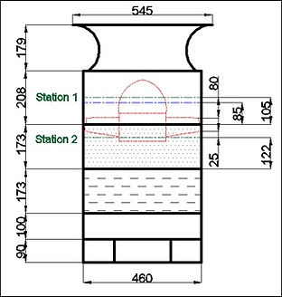
Figure 17: The meridional view of the fan rig, to scale
Figure 20: The schematic of the connecting instruments


Figure 21: Throttle Components
Table 3: Part list of the gearbox of the throttle device
Figure 22: Gearbox housing with the gears aligned together

Figure 25: Fully open(right)/ fully closed (left) of the throttle


Figure 23: Throttle cone attached to base
Figure 24: Throttle adjustment methods
Blade deflection Test

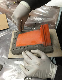
Step 4:
-
Removed the clay from the mould.
-
The surface of the master pattern and silicon mould were cleaned from any dirt.
-
The surface of the silicon mould was sprayed using release agent to prevent bonding.
Figure 9: Apply release agent


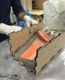
Step 3:
-
Mixed silicon rubber & catalyst with a ratio of 100:5
-
Poured the mixed silicone gently into the lowest point of the set-up box
-
The silicon rubber was allow to be cured for 24 hours
Figure 8 : Pouring silicon rubber to the mould
Table 2: Mix ratio by weight of polyurethane F190
Figure 11: The mixed resin is fully filled into the mould
Video: Removing the casting blade from the mould
3. Modification of the Throttle Device
January 2016- September 2016
Final Master's Group Project
University of Sussex